
  |
This topic explains how to partition a large IPXTM internetwork into routing areas. Because large internetworks are typically linked by one or more WAN connections, the guidelines and examples provided in this topic are oriented primarily toward WAN connections, which require other Novell® products or third-party products in addition to NetWare® 4.1x software or IPX Upgrade for NetWare Servers. However, the information in this topic can still help you partition a purely LAN-based internetwork.
You should read this topic if
If you do not know how many network numbers your internetwork has, refer to Step 1: Determine the Size of Your Internetwork.
NOTE: IPX Upgrade for NetWare Servers does not provide filtering capability. Filtering utilities are available with any product that contains NetWare 4.1x .
This topic includes the following sections:
This section explains what routing areas are.
This section introduces the Novell Network RegistrySM service and explains how to use the services it provides.
This section presents guidelines to help you determine how you should partition your internetwork.
Routing areas establish hierarchy within an IPX internetwork. For growing networks, routing areas allow for better scaling---more LANs, servers, and routers than otherwise possible. Routing areas also separate an internetwork into manageable components, which is desirable for administrative simplicity.
Two 32-bit numbers---a network number and a mask ---identify a routing area. Together, these numbers constitute the area address. Here is an example:
08068500 (network number)
FFFFFF00 (mask)
The default values for the network number and mask are as follows:
The address and mask are both set to zero to ensure compatibility with future versions of NLSP software. Zero values mean that all NLSP routers operate in a single routing area.
IMPORTANT: Although any product that contains NetWare 4.1x allows you to configure the area address and mask, accept the default values and use RIP to partition your areas as described in the next topic.
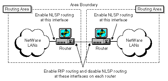
You can create routing areas by running RIP on the network interfaces that link the areas. Figure 3 shows two routing areas partitioned by RIP.
Figure 3
Creating Routing Areas Partitioned by RIP
The following steps summarize how to configure the interfaces:
Enable NLSP routing on each router.
If you are using any product that contains Novell Internet Access Server 4.1, complete the following steps:
Load NIASCFG, then select the following parameter path:
Select Configure NIAS > Protocols and Routing > Protocols > IPX
Set the Routing Protocol parameter to NLSP with RIP/SAP Compatibility .
Save your changes.
If you are using IPX Upgrade for NetWare Servers 6.5a, load IPXRTR as follows:
LOAD IPXRTR ROUTING=NLSP
On the network interface that links the areas, turn off NLSP and turn on RIP and SAP.
If you are using any product that contains Novell Internet Access Server 4.1, complete the following steps:
Load NIASCFG, then select the following parameter path:
Select Configure NIAS > Protocols and Routing > Bindings
Select the interface.
Select Expert Bind Options , then select RIP Bind Options ; set the RIP State parameter to On .
Return to the Expert Bind Options menu, then select SAP Bind Options ; set the SAP State parameter to On .
Return to the Expert Bind Options menu, then select NLSP Bind Options ; set the NLSP State parameter to Off .
Save your changes.
If you are using IPX Upgrade for NetWare Servers, bind IPX to the interface as follows:
BIND IPX boardname NET=network_number RIP=YES SAP=YES NLSP=NO
Although NLSP is disabled on the interface at the area boundary, each router still imports the routes and services from the connected network into its own routing area.
You can use routing areas to prevent RIP and SAP traffic on one network from flowing to another. For example, suppose you want to prevent some users from gaining access to the accounting services on a particular network. You can use service filters to restrict access to those services.
IMPORTANT: You cannot filter routes or services within a routing area, but you can filter routes and services between areas at the area boundaries. If you want to restrict Network-layer access within a routing area, you can filter IPX packets.
If you use route and service filters, you must configure the same inbound and outbound filters on all NLSP routers connected to the same LAN within the same area. With NLSP, all routers in the same area share the same link state information; however, a single system called the Designated Router imports routes and services for the entire network. Therefore, if you configure an inbound route or service filter on one---but not all---NLSP routers, and that router is not the Designated Router, the filter might have no effect.
NOTE: IPX Upgrade for NetWare Servers does not provide filtering capability. To configure filters, you must use a product that contains NetWare 4.1x .
Business organizations, each with its own enterprise network, sometimes merge or agree to share information. Or, these same organizations might want to connect their networks to a larger public internetwork to use the services it provides. This means that all network numbers throughout the connected organizations must be unique.
For this purpose, Novell offers the Novell Network Registry . The Novell Network Registry service assigns and tracks IPX network addresses and organization names. The Novell Network Registry enables participating organizations to share data between interconnected NetWare networks without name and address conflicts.
The Novell Network Registry assigns a contiguous block of IPX network addresses that are unique to your organization. The size of your address block depends on the number of NetWare LANs and servers in your IPX internetwork, including any additional LANs or servers you anticipate installing over the next two years.
To learn more about the Novell Network Registry, or to reserve a block of IPX network addresses, call 1-408-577-7506 or send Internet e-mail to registry@novell.com. You can also send e-mail by way of the Novell NHUB system to registry@novell. Ask for the publication The Novell Network Registry.
This topic uses examples to show how to define routing areas in an IPX internetwork.
NOTE: There are many ways to partition an internetwork into areas. This topic provides only a few examples of how this can be done.
Apply the following guidelines when defining routing areas in your internetwork:
Make a sketch of the internetwork. A graphic representation can help you identify area boundaries and key routers more easily.
Identify the routers that make up the core network infrastructure. These routers typically form the corporate backbone network. A core area that uses backbone routers is shown in Partitioning an Internetwork That Uses a WAN Backbone.
Identify the routers that feed one or more LANs. These feeder routers service LANs that typically represent functional groups, such as remote sales offices, an engineering department, and so on. An example of feeder routers is shown in Partitioning an Internetwork That Uses a Transit LAN.
Do not enable NLSP on the interfaces at area boundaries. Two routers running NLSP at an area boundary automatically become neighbors and join their respective areas into a single area. Run only RIP at an area boundary, as shown in Figure 3. However, a router in one area can run NLSP on a transit LAN while routers to other areas run RIP. An example of this is shown in Partitioning an Internetwork That Uses a Transit LAN.
Avoid partitioning routing areas across WAN connections. Doing so forces RIP to run over the WAN connection, which, along with SAP, consumes network bandwidth. Wherever it is possible, run only NLSP over the WAN connections in your internetwork. Partitioning an Internetwork That Uses a WAN Backbone and Partitioning an Internetwork That Uses a Transit LAN show how an internetwork can be partitioned to keep WAN connections within a single area.
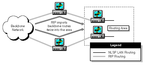
Avoid having more than one RIP connection between a backbone router and a single routing area. Otherwise, the routers import the same routing and service information through each connection from the backbone into the routing area. This can double the routing traffic flowing into the area. Figure 4 shows the type of area configuration you should avoid.
Figure 4
Why You Should Have Only One RIP Connection between a Backbone Network and a Routing Area
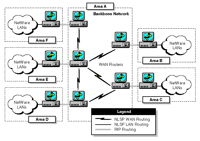
This topic explains how to define areas on an internetwork that uses a central backbone of WAN routers. Figure 5 shows a large IPX internetwork linked by five WAN routers that form the network backbone. Each WAN router is connected to a LAN router that services a small group of NetWare LANs. Without the benefit of NLSP or routing areas, RIP and SAP traffic from all the NetWare LANs traverses the backbone and consumes a large percentage of the available bandwidth.
Figure 5
Routing Areas in an Internetwork Connected by a WAN Backbone
This internetwork is partitioned as follows:
Area A--- The backbone network of WAN routers forms one area.
Areas B through F--- Each group of NetWare LANs forms its own area.
NLSP routing is enabled on the interface between each LAN router and its respective group of NetWare LANs.
This topic explains how to define areas on an internetwork that uses a transit LAN . A transit LAN is typically a high-speed LAN---such as a high-speed token ring or Fiber Distributed Data Interface (FDDI) ring---that serves as a crossroads for all traffic on the internetwork. A transit LAN can link several routing areas.
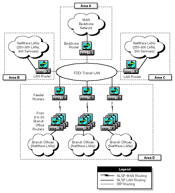
The internetwork in Figure 6 has six routers connected to an FDDI transit LAN:
Figure 6
Routing Areas in an Internetwork Connected by an FDDI Transit LAN
This internetwork is partitioned as follows:
Area A--- The backbone router and the backbone network form one area.
Because the backbone router is running NLSP on the interface to the backbone network, it incorporates the route and service information it receives from the LAN routers into its Link State Packets (LSPs). The backbone router passes these LSPs to the backbone network.
Areas B and C--- Each LAN router and its group of NetWare LANs form a separate area.
Area D--- The feeder routers, branch office routers, and branch office LANs form one area.
To exchange routing information, the feeder routers use NLSP among themselves and RIP with the three other routers on the transit LAN.
When you configure the network interfaces, start with the routers on the transit LAN---the backbone router in area A, the LAN routers in areas B and C, and the feeder routers in area D---then work out toward the branch office LANs.
You can use the IPX network management console (IPXCON) to make sure you have configured the routers correctly. Using the internetwork shown in Figure 6 as an example, you would load IPXCON on one of the routers and view the neighboring routers on the transit LAN. The three feeder routers running NLSP on the transit LAN should show each other as neighbors. They should not, however, show the backbone router or the two LAN routers as neighbors. The backbone router and the LAN routers should have no neighbors on the transit LAN.
For information about how to use IPXCON, refer to Managing in the IPX documentation .
  |